Long Overdue Firmware Overhaul – Bit Banging

When I first started at MNS, one of my main tasks was to decode new TV’s and remotes we receive from installers and add that remotes functionality into our IRU firmware. The firmware we were using was created by my boss and mentor @VernonBreet. The earliest date of the firmware I could find was version 6.1.00, dated 06 September 2011 but it was derived from versions dating back to 2008 (if not earlier). The last major update in the firmware was done on the 4th June 2012. Since then, I have added numerous models of TV and remote combinations to the firmware. The only minor change I have made to the functionality of the FW was adding a new hand held unit (HHU10) to the code which incorporated light dimming for the patients. Other than that, there has been no fundamental changes to the FW.

So, if the FW works and has been working for years, why change it?

There are several reasons why the firmware needs to be recreated. The FW was done in MPLAB IDE v8.66 using BoostC Complier version 7.03 (from SourceBoost). Currently, I am still doing the TV updates in the firmware using MPLAB v8.89 and BoostC v7.051. At the time of writing, the FW consists of – 25 C files, 4 header files and over 12992 lines of code. The code has become confusing. I’m sure it would take me a month to explain to someone how it all works and how to add new code for TV’s. The complier is old, the IDE is old and giving issues when using debug headers. It normally takes about half a day for me to decode a TV and program a new PIC, doing it the same way I have since I started. The FW was created for a PIC12F683. We are planning on using the PIC12F1822 which is half the price of the 683. These are just a few of the reasons for the overhaul. But, frankly, I am just tired of having to manually create a new FW version for each TV, remote and DSTV combination we get. I want to create a more automated way of programming remotes into the FW (think of universal remotes). Even though I was told that if I were to do this, that there would no longer be a reason to employ me J.

What are some of the challenges and issues?

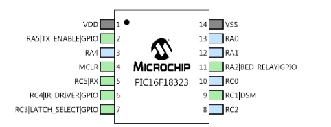
New IDE, new complier. MPLAB X has the option to import MPLAB v8 projects. I have tried this before but was put off it immediately due to the number of macros that would need to be changed because the complier would now be XC8. Also, the code is complicated. I felt that it would be better to redo it from scratch, adding functionality that I want. Another issue is that the new PIC we use must be pin for pin compatible to the 683. We have so many TVIR boards in the market, that the new PIC and FW would have to offer backwards compatibility. This is great because the 12F1822 has all the peripherals that I would need so it shouldn’t be an issue as I could easily and quickly set that all up using MCC. BUT, I can’t. The 12F683 didn’t have built in PWM, UART and DSM. So, when the board was designed and the pin functions were assigned, I’m guessing they were assigned at random. This is now an issue as I can’t use the built-in peripherals on the 1822 as the pin assignment does not align to the 683. But it’s not an issue in the bigger scheme of things. It’s just an issue to me because I can’t quickly setup peripherical such as the UART using MCC and I must manually bit bang the data coming into the RX pin. So, this is where we start.

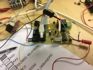
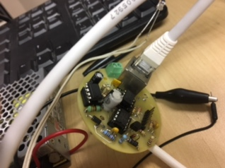
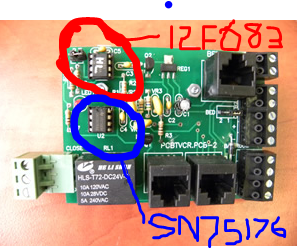
Below is out MP-TVR board which connects to the Bed Head Unit. This receives the 485 comms from the BHU and controls the IR and light relay, among other things. Pro editing skills.

UART

I decided to start with getting the comms working first as I knew this would probably be the most difficult to get correct. We have both the TX and RX connected to the 683 BUT we only make use of the RX in the old FW as there was no real need for the TX.

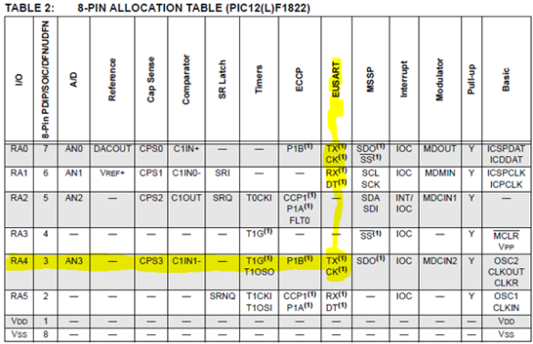
From the above image, you will see that we use a SN75176 to convert the RS-485 comms that come from the BHU to UART for the 683. The RX output pin of the SN75176 goes to RA4 (pin 3) of the 683 and the TX input of the SN75176 comes from RA1 (pin 6) of the 683. The old FW used a UART.c file for the comms but the RX function has been modified to read the incoming TTL on the pin by bit banging. I had hoped that the RA4 pin on the 12F1822 was the RX peripheral but when I looked at the data sheet this was not the case, as per the below.

Most newer microcontrollers will have built in UARTs that can be used to receive and transmit data serially. UARTs transmit one bit at a time at a specified data rate or BAUD rate. This method of serial communications is sometimes referred to as TTL serial (transistor-transistor logic). Serial communications at a TTL level will always remain between the limits of 0V and Vcc. A logical high is represented by Vcc and a logic low by 0V.

The above picture shows a TTL signal sending a 0b01010101

You will see that the signal initializes with a start bit which is a logical low. It then transmits 8 bits of data starting with the least significant bit. After 8 bits of data have been sent, there is a stop bit which is a logical high. You could also have an optional parity bit in between the MSB and the stop bit. But for our purpose we are not using the parity bit.

It is easy to calculate the timing of the bits using the formula – Bit Length = 1 / Baud Rate. In our case, I thought we were using a Baud rate of 9600 to send serial comms from our BHU. This meant that I should be able to scope the bit lengths to 104us but this was not the case. I was in fact getting about 50us which meant the actual baud rate that was used was 19200. I will try find the BHU source code and check that just to confirm.

Bit Banging the UART RX

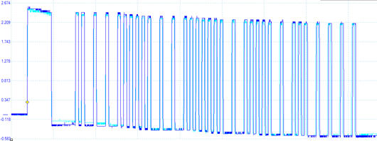
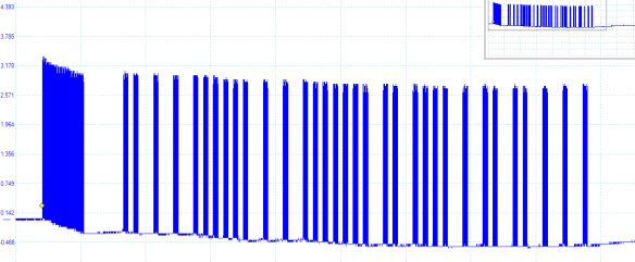
Knowing the above, we now just need to write a function that would wait for the start bit to end then read the value of the Rx pin half way through the bit time, 8 times over. We can just ignore the stop bit at this stage. Below is a screen shot of the scoping that I did on the Rx Pin receiving a 0x35. You will see my sample timing is not 100% perfect but it is still working none the less. I am toggling a pin (the red scope) every time I read the Rx pin.

Below is the function I used to obtain the above. *** trying code wrapping again ***

char receiveChar (void){
    char RxBuffer = 0x00; // used to store received character
    if (RX_PIN_GetValue() == 0){ // is this a start bit
        __delay_us(HalfBitTime); // delay half a bit time into the start bit
        // Receive 8 bits of data
        for (int bitCount = 0; bitCount < 8; bitCount++) {
            //DEBBUG_LED_SetHigh(); // Only here to scope and make sure the pin is being read at the correct time
            if (RX_PIN_GetValue() == 1){ // is the RX Pin high?
                RxBuffer = RxBuffer | 0b10000000; //set least significant bit
            }
            //DEBBUG_LED_SetLow(); // Only here to scope and make sure the pin is being read at the correct time
            if (bitCount < 7){  // check for the last bit
                RxBuffer = RxBuffer >> 1; //bit shift 1 to the right
            }
            __delay_us(BitTime); // delay 1 bit time before reading the pin. This should sample the pin half way through the bit
        }
        NOP(); // here for debugging
    }
    return RxBuffer;
}

LED Light Dimmer using PWM

We got a requirement from a client to create a LED light dimmer using Pulse Width Modulation (PWM) for a potential product they are looking at. The specs from the client were – they needed 3 buttons (ON/OFF, Light UP and Light DOWN), 4 status LEDs and they wanted the intensity of the up and down steps to step as 25%-50%-75%-100%.

At first we wanted to use an 8 pin IC but even if I were to charlieplex the LEDs and buttons, it would still require a minimum of 6 pins. I had some PIC16f18323 in my office, which are 14 pin ICs so I decided to start the dev using that, and if it needed to be changed then we could just do so.


Using PWM to dim LEDs

PWM is a common peripheral on all PIC MCU devices. PWM is a way to use a digital output to vary the high time, to create a variable output or square wave. If the PWM signal runs at a fixed frequency, then changing the high time of the signal will also change the low time of the signal. The amount of time the signal is high is typically referred to the pulse width. That pulse width relative to the period of the signal is referred to as the duty cycle. The period of the signal is defined as the time from one rising edge to the next rising edge of the square wave signal and is inversely proportional to the PWM frequency. The period can be calculated by using the formula: Period = 1/Frequency.

By using PWM, it provides the ability to ‘simulate’ varying levels of power by oscillating the output from the microcontroller. So basically, if, over a short duration of time, we turn the LED on for 50% and off for 50%, the LED will appear half as bright since the total light output over the time duration is only half as much as 100% on. When using this method to dim a LED, the important factor here is the duration of the period – if we turn the LED on and off too slowly, the viewer will see the flashing of the LED and not a constant light output which appears dimmer. So it is important to consider how slowly we can flash the LED so that the viewer does not perceive the oscillation. The minimum speed of an LED oscillating which can be seen by the human eye would be a speed of 70Hz. So for this I decided to use 250Hz to reduce the chances of a visible flicker.

So basically, the longer the pulse width or high signal is on during the period, the brighter the LED will be. And inversely, the shorter the pulse width, the dimmer the LED would appear. So as per the below image, if we have a duty cycle of 100%, the LED would appear at its brightest. A duty cycle of 0% would turn the LED off.


Setting up PWM using MCC

We can easily setup the PWM in the PIC16F18323 using MCC in MPLABX. In order to use the PWM we will need to add a timer to the peripherals, to be using in conjunction with the PWM peripheral. As I mentioned above, I want to run the PWM at 250Hz. The below pic is the setup of the timer in my MCC.

Below is the setup of the PWM in MCC. I have output the PWM onto pin RA5 of the PIC. You will see that in the PWM window in MCC, you can adjust the duty cycle value and it will give you the value which you need to input into the function that MCC generates, in order to get that percentage duty cycle. Here you will have to enable the PWM and tell it which timer it is using, timer 2 in my case. Another thing to note is the polarity of the PWM. I am not going to get into this now but it is basically used to adjust whether the square wave signal generated on the PWM pin is active high or active low. So if you are driving the LED directly off of the PWM pin (RA5), you would set it to be active high, which would also make more sense with the duty cycle not being inversed. I had it set to active_lo because the RECOM RCD-24-0.35 that we used to generate the signal on a 40V line, inverted the signal it received.

You might notice that the values for the duty cycle percentages are -1 of what the duty cycle * 10 would be. You can check the datasheet of the PIC you are using and it will give you the formula for calculating the duty value that you would need.

Using the MCC Generated Function

So after generating all the MCC files, there is a really easy function that you call to adjust the pulse width of the PWM. I have put a screen shot of the generated function below. As well as an example of it being called at a 50% duty cycle, using the value from the above pics.

That is basically it. I am not going to include all my button / LED and other code cause it isn’t really necessary. I have uploaded a short video which we sent as a proof of concept to the client, which can be found here – https://www.youtube.com/watch?v=7I3k1On7vuE

Driving the Actual LED Light

The client gave me a sample of the LED light they plan on using as well as the PSU they would like to use for the product. The issue now, is that the PSU they want to use is 40V. We found a really cool DC/DC-Converter or constant current LED driver, that will take an input of 40V from the PSU as well as the PWM logic at 5V and output a 40V PWM signal. You can get more info on the Recom DC/DC converter here – Recom Link

Below is a screenshot from the datasheet. You will see that they invert the PWM signal and that is why I had to change the PWM polarity of the chip output to active low.

Powering the PIC

Next we had to look at getting a DC/DC step down module to get the 40V from the PSU to 5V for the PIC. We found a cheap module, in the below pic, that would fit well into the product. Even though the module says it only takes 1.25V-35V, it is able to step down 40V.


Our New 3v IP TV Board (Part 2 – Coding)

So, I’m am not going to post and go through every step of my code. This is just a place for me to reference parts of code that I would like to come back to. Have problems with. Learning about new controls.

The basic flow process on the IP TV Board, is that it waits for a command to come from the BHU then interprets that command and processes it accordingly. On the old TV board we were polling the rx pin constantly checking for any comms from the BHU. We have decided that we will use interrupts on the new version so that we can put the board into a sleep mode until commands are received.

Microchip DSM – What How Why

With the previous version of the TV board, we used a pic12f683 and generated the IR code by bit banging the specific pin that controlled the IR LED. We have decided this time around that we will use the DSM to generate the 38Khz transmission needed to drive the IR LED. But how does the DSM work.


Looking at the datasheet, we can see that there are multiple sources that can be used for both the modulator signal and the carrier signal (being the frequency the DSM operates at).


While reading up on DSM I found a few examples using SPI and UART to supply the modulator signal to the DSM. At first I thought that using SPI would be a good idea as we could just supply the SPI with the IR code that we want the DSM to run. I used a snippet (below) from a code example in the microchip technical brief TB3126. After trying this out, it became clear that it would be difficult to use the SPI as the source due to the timing involved with sending IR code.

From running this example, I decided that it I would have more control over the IR transmission if I manually operate the DSM modulation source. Below is a screen shot of the MCC I used. The output pin is currently set to RC3 because it’s the easiest to connect the O’scope to.

I created 2 functions to test the manual control of the DSM. The first one being the protocol function. It starts with sending the AGC burst for 9ms followed by a 4.5ms space, by straight toggling the MDBIT (manual control). It then sends the address, then inverted address, then command and finally the inverted command. The second function is used to toggle the MDBIT on then off for 560us. The function is sending out the MSB first. It then checks to see if the bit is a logical 1 or 0 and then delays 1.68ms for 1 and 558us for a 0 before we issue the next instruction. It lastly shifts the bytes left (next LSB into MSB) before looping.
Ok so, I’m going to try wrap my code below (using a csharp wrap??). I’m typing this up in word so I am hoping that the wrap will pull through to the blog when I publish. !EDIT lol I just pasted the code here…. Looks so horrible. I really hope the wrapping works. !!EDIT didnt work… Had to edit it.

void sendProtocol_NEC(unsigned char address, unsigned char command)

{

MDCONbits.MDBIT = 1;

    __delay_us(8999);

    MDCONbits.MDBIT = 0;

    __delay_us(4490);

sendByte(address);

sendByte(~address);

sendByte(command);

sendByte(~command);

__delay_ms(40);

}

void sendByte(unsigned char byte){

    unsigned char i;

    for(i=8 ;i&gt;0;i--){

        MDCONbits.MDBIT = 1;

        __delay_us(561);

        MDCONbits.MDBIT = 0;

        if(byte &amp; 0x80){

            __delay_us(1686);

        }

        else {

            __delay_us(558);

        }

        byte = byte << 1;

    }

}

Below is the result of running the code and sending an address of 0x7F and a command of 0xFF. Its looking really promising!!!!!

But….. there is a problem. The carrier frequency of the IR code should be at 38kHz. When I take a closer look at what I am currently getting, it is at 8.4kHz. Ok this won’t work then.

Having a look at the MCC configuration (a few pics up) we will see that I am using the high frequency internal oscillator to drive the carrier signal. I am running the crystal at 16MHz and the clock divider at Fosc/4. I’m guessing that playing around with these will adjust the frequency of the carrier signal BUT I thought that I might as well change the source to the PWM and set that up. It will probably be easier.

So, again, using MCC we add both timer2 and PWM5 to our project. Using a postscaler (should I use prescaler???) of 1:10 on tmr2 we are getting a PWM frequency of 38.46kHz. Will check the math later….


Hmmm will have to check this out. But lets run it as such and see what the outcome is.

So after scoping the IR signal on a reciever board, the outcome is looking good. It seems as though the frequency is running at 38kHz. Time to test it with some actual remote IR code.

We have a Sinotec TV in the office, that I have previously decoded. I am going to use this TV as a test case cause it uses NEC protocol. So having looked at the decoding I done for this TV previously, there are 2 small issues that I see that I will have to address. As per http://www.sbprojects.com/knowledge/ir/nec.php the standard NEC protocol runs the AGC burst for 9ms whereas this Sinotec only runs the AGC burst for 4.5ms. Another difference is the addressing. The norm would be to send out the 8 bytes of the address then send them again but invereted. This remote does not invert them and simply sends them again as is. The commands are invereted after the first send. So, going to quickly change that and test it out.

In the below pic you will see the result of running an address of 0x70 and command of 0x30, being the power command. The light blue is the scope of the actual power button from the remote. We note 2 things, the first being that over the duration of the burst, the timing gets out of sync. Second being that we are missing the 32nd bit.

I have fiddled around with the timing of the: AGC burst, space, carrier high and the logical 1’s and 0’s. I also added a random single bit at the end for the one that was missing???? I will need to look further into this (EDIT: so it seems like the last command bit is being processed via the delay but there is no following bit to toggle the DSM. So adding a final pulse is correct and should work for all remotes). Below was the scope result of the changes. The timing is not 100% but it IS good enough for the NEC protocol.

Its looking good! I tested it on the TV and it turned on. I also added the other commands (PGM UP, PGM DOWN, VOL UP and VOL DOWN) and tested them all on the TV and they are working! Awesome. Although… There seems to be an issue with the PGM Down UART signal coming from the BHU. It is occasionally sending out POWER commands… This sucks because I had it tested by 4 different people in the factory and reported it working fine. But its fine I will have a look at it. I already have a fix in mind AND it might give me an opportunity to do a basic blog draft about the BHU.

So the code is working as a proof of concept now. There is still a lot more that needs to be done to it, such as adding RC5 and DSTV protocols. I will make another post when it comes to adding those protocols. But for now, the code is working good enough (other than the PGM – issue) for our exhibition in Durban in 4 weeks time. Going to upload to GitHub and then take some pics of the hardware to show and then post this.


1 – New handset with a new resistor ladder for 3v3

2 – New TVR IP board (running above code)

3 – New BHU board to integrate to the IBX system. Getting power over the Ethernet cable

4 – TV turning on via POWER button press.

*** EDIT ***

So I realised that I forgot to show a few small changes that I had made while writing the blog, as well as mentioning a few things. Initially scoping RC3 was to make sure that all my settings for the DSM were correct and that toggling the MDBIT would actually toggle the DSM output which was set to RC3 at that stage (I didnt post any screen shots of that). I then changed the DSM output to RC4 as the board I was using, requires.

At first, I thought that it would be easier to use the HFINTOSC to generate the 38kHz frequency on the DSM output. But after struggling for a little bit, I decided to rather use the PWM to generate the frequency. Below is a screen shot of the MCC settings for the DSM that I ended up using. The PWM and Timer settings are as per above screen shots.

Untitled

Below is the scope reading of the actual DSM output pin (RC4) using the PWM as the source to generate the 38kHz frequency.

Untitled2.png


Our New 3v IP TV Board (Part 1 – Overview)

We have partnered with a company from Spain that has designed a really amazing IP based nurse call system. We will call it IBX for now. Although their entire design is amazing, there are parts of it that does not accommodate the ‘African market’. In order to integrate our products with IBX we decided to redesign the hand held unit, bed head unit (BHU) and the TV controller board (TVR). The hand held unit was the easiest of the 3 seeing that we just had to redo the resistor ladder. I have finished the bed head unit, but unfortunately there is no post on that. So this is picking up from the first stages of development of the TV Controller board.


The new TV controller board is not completely new. It’s an adapted design of our old TVR-CON board. The old board used a PIC12F675 and operated at 5v. For the new board we decided to run the board at 3v3 using a PIC16F1823 but we currently don’t have stock of that so I am using PIC16F18323, the main difference being that the 18323 opperates better at 3v3, so we might just end up staying with it.


Operation Breakdown


  • Receiving serial comms from the BHU telling it what buttons have been pressed
  • Operating the bed light relay
  • TV infrared control using DSM
  • Other stuff place holder
  • Other stuff place holder


MCC Generated Code


Below is the current pin setup as of February 2017. You will notice that we are not using the TX yet cause the pin is the same as the ICSP DATA pin so it tends to cause issue when debugging in circuit. Also, for the initial phase of the application, we will not be using the TX. We have plans for it at a later stage, so will do with out it for the moment.


Baud rate is set to 57600 as per the BHU baud rate. We went with this to differentiate the new design from the previous boards which operated at 19200 if I am not mistaken


This is the current DSM setting I am using but I will review it when I get to this section


Workflow


Current operation of the chip will be: The chip will sit in an idle state until it receives serial comms from the BHU board via pins 4 and 5 of the CAT5 cable. The commands received on the UART will then be decoded to determine what the button pressed on the handset was. In the case that the button was a TV control button, we will then drive the relevant, pre programmed, IR code for that TV. This will be done via the DSM. In the case it is the bed light, we will then toggle the replay.

For easy reference, the commands sent by the BHU are below. **** I might have to check for a DISCONNECT command now that I’m thinking about it ****


The New Year Comes with Resolutions

So I started this blog in April 2012 and it ran good for the first year or so. Then, it kind of just died a natural death. I check a folder that I have on my PC where I have a number of draft blogs saved and I was shocked to see about 8 unpublished posts.


So why do I go through all the effort of blogging the work I do, only to have all that info sit in a draft folder on my PC? Reason – my slight OCD.

When I blog my work, the OCD kicks in! The correct font needs to be used. Everything needs to be the correct font size. Images need to be tabbed and scaled correctly. I cannot bring myself to posting a blog unless it looks like a ‘news site’ ready post. But herein lies the problem. I tend to focus more on making sure that indents are correct, rather than getting work done and info on it posted.


So as the new year comes with resolutions, one of mine is to start posting more of my draft blogs from now on. To achieve this, I will no longer let the formatting of future blog posts bother me at all. So if you suffer from a small case of OCD like me, let this serve as your warning that things might not be pretty from here on out.

Microchip’s Maxi Web – TCP-IP Board

Introduction to the board

This board, also known as Olimex, will allow you develop easy Ethernet connectivity applications. It has everything you would normally need for such applications: power relays, LCD display, analogue inputs for connection to sensors, digital optoisolated inputs, trimmer potentiometer, temperature sensor and an Ethernet connector. Another awesome feature about this board is the ability to command most of the board features through a pre-built web interface. This comes in handy with regards to MNS as we will be able to receive updates from the Mimic boards installed on different floors in hospitals at a central point.

The PIC18F97J60 has 128KB flash programming memory. The on board AC/DC converter makes the board very tolerant to the external power supply, which could be in the 9 – 25V DC or 7 – 18V AC range.

Maxi Web TCP-IP board

Features

  • PIC18F97J60 microcontroller with embedded Ethernet MAC and PHY and 128KB Flash programming space
  • 1Mbit on board serial flash for web pages storage
  • ICSP/ICD connector for programming and debugging with PIC-ICD2 and PIC-ICD2-POCKET.
  • Temperature sensor
  • Trimmer potentiometer connected to analogue input
  • Two relays 10A/250VAC
  • Four optoisolated digital inputs
  • Twelve analogue inputs on terminal block
  • Two buttons
  • LCD16x2 with backlight
  • RS232 interface
  • Ethernet interface
  • Complete web server and TCP-IP stack support as per Microchip’s open source TCP-IP stack
  • Terminal block for power supply works with 9-25 VDC power supply
  • Extension header to connect to other boards
  • Dimensions 120×108 mm (4.72×4.25″)

Documents

Making an ICSP Programmer / Debug Adapter for the Board

The board comes with an ICSP connection that allows us to re program the PIC18F97J60 microcontroller. Below you will see an image explaining the pins on the ICSP connection.

ICSP Configuration

PGD    I/O    Program Data. Serial data for programming.

PGC    Input    Program Clock. Clock used for transferring the serial data.

In order to re program the microcontroller you will need to connect the ICSP to a PICkit programmer. As per the below image, you must make sure that your pins are correctly aligned (pin 1 of the programmer is connected to pin 1 of the ICSP).

PICkit 2 connected to the ICSP of the board to program the microcontroller

Programming the Board with the Newest Firmware

Once you have loaded the hex you will get the above warning

Successful writing of the hex to the microchip

Pre and Post Programming of the Correct HEX

We have updated the default hex that comes with the TCP-IP board to suit the application of the board in the Nurse Call environment. The boards come with a ‘TCPStack v5.00’ already programmed into the microchip. The TCPStack v5.00 has a static IP address programmed into the microcontrollers. The static IP address is 192.168.0.95. As we require the IP address to be dynamic, thus we have changed the hex to obtain an IP address from the router. The latest version of the TCPStack at the time of publish, is version ‘TCPStack v5.41v2’. Below you will see 3 pictures of the board during 3 stages of the programing and testing.

The default settings of the board


Once programmed the version changes as well as the IP address

Once you connect the board to your network you will notice that the IP changes

Once you have the board connected to the network and it has received a DHCP IP address, you can run a program called ‘MNS Ethernet Listener Discoverer’. The will search for all the Maxi Web devices connected to your network. This is a very handy program as it displays the IP Address, Host Name and MAC Address of the devices that it detects.

Uploading the HTTP server

Once you have uploaded the latest hex file to the microchip and you are able to discover the board on the network, you will have to upload the web server to the board. If your board is discoverable on the network, you can open your browser and enter the IP address that is displayed on the boards LCD into the browser. In my case I entered the IP address 192.168.16.187. The page will then prompt you to upload a MPFS Image onto the board. If you cannot access the page from the initial page then you can type the following into the browser to access the page <IP_ADDRESS>/mpfsupload i.e. I would type 192.168.16.187/mpfsupload

Once you access the upload page you will be able to browse for the MPFSImg2.bin file and upload it to the board. The upload takes about a minute to complete. The browser might seem like it has crashed during the upload but just give it time to complete. Once completed you can click on the ‘Site main page’ link and you should be taken to the main page.

Uploading the MPFS Image

After uploading my MPFSImg2.bin file, I ran into a problem where the page was not in the correct format (see below image). After downloading a whole bunch of MPFSImg.bin files and still have no success, followed by a Google marathon to try and correct the issue, I realised that my MPFSImg.bin file was missing a define header. I used a tool provided by Microchip called ‘Microchip MPFS Generator’ to rebuild the MPFSImg.bin file and it worked from there.

Incorrect MPSF Image uploaded

Editing the Webpages

You can easily edit the webpage of board and simply upload the newer page once the editing is complete. To edit the webpages you simply have to navigate to the following directory, TCPIP/Demo App/WebPages2 , and you can start editing the webpages from there.

Please note that if you have edited any of the webpages you will have to rebuild the MPFSImg2.bin file and reload that onto the board for the changes to take effect.

Microchip MPFS Generator

Microchip has provided a MPFS Image Generator that we have to use to rebuild our MPFSImg2.bin files after we have edited the webpage. Once you have completed editing the webpages you can simply run the app which looks as follows.

Microchip MPFS Generator

You will have to make sure all the settings are correct in order for the generation to be correct. Follow the below setting examples.

  1. Source Directory: Point this to the directory which contains the webpages which you wish to generate into the .bin file
  2. Output: As we need to upload a BIN Image onto the board, make sure that you have selected it. The advanced settings tab can remain on all its default settings
  3. Output Files: This is the directory where the generated BIN file will be stored
  4. Upload Image To: We will not be using this option so you can just un check the check box

Once you have completed steps 1 to 4, you can the click the generate button to generate the new MPFSImg2.bin file, which can be uploaded onto the board.

Changing the MAC Address

Once you have uploaded your desired webpage onto the board, it is a good idea to give that board a MAC Address which is specific to that board. It is really simple to change the MAC Address of the board. Once you are on the boards webpage, simply click on the ‘Network Configuration’ tab on the left side of the screen. You might be prompted to enter a username and password. The default username is ‘admin’ and the default password is ‘micro’. Once you have passed the security check you will be able to edit the MAC Address as well as the Host Name of the board as per the below image.

Network Configuration

Currently we are defining all the MAC Addresses with a standard of 00:04:A5:5A:00:11 where boards ending in the range of 00:01 to 00:99 are all test and demo boards. You will see that we have given the boards the Host Name of ‘LISTNER’ followed by a unique ID which consists of the last 4 digits of the MAC Address.

We are currently working on a way of automating the process of assigning the boards a MAC Address.

.lnk Problems

I got a call from Tania at JJ Comms informing me that all her desktop icons and start menu icons were opening Adobe Reader instead of the specified program. After reading up on this I discovered that her .lnk file association had been set to Adobe Reader. The .lnk is the extension used for shortcuts hence every shortcut opened was opening Adobe. You will see, as per the below image, the .lnk ‘Current Default’ is meant to say ‘Unknown Application’.

Unfortunately, once it has been set, you cannot just change it back. I found a site that has a bunch of registry downloads to fix broken file associations. Once you have downloaded the correct file, you just extract it then right click on the file and click MERGE. This should sort the problem out after a restart.


http://www.winhelponline.com/blog/file-asso-fixes-for-windows-7/

TV Remote Decoding Continued

Up until today, all of the TV’s we have been getting have used NEC Protocol in their remotes. We had one TV, a JVC LT-19N300, which used a modified version of the NEC Protocol. Instead of the header being 9ms as per the standard, they had decreased the header time to 4.5ms as per the below image.

RC-5 Protocol

Today I got a HiSense LEDN19T28 that uses RC-5 Protocol in the remote. This protocol has some really interesting features.

  • 5 bit address and 6 bit command length (7 command bits for RC5X)
  • Bi-phase coding (aka Manchester coding)
  • Carrier frequency of 36kHz
  • Constant bit time of 1.778ms (64 cycles of 36 kHz)
  • Manufacturer Philips

Below is an image of the Modulation of the Logical ‘1’ and Logical ‘0’

You will see that all the bits are of equal length. Each bit had a total length of 1.778ms. You will also notice that half of the bit is filled with a burst of the 36KHz carrier frequency and the other half of the bit remains idle. A Logical ‘0’ is represented by the burst being in the first half of the bit while a Logical ‘1’ is represented by the burst being in the second half of the bit.

Below is an image of the typical pulse train of an RC-5 message.

The first two bits are the start bits and are always a Logical ‘1’. The third bit is a toggle bit. This bit is inverted every time a button is released and pressed again. The inverting of the third bit is not button specific. For example, if you were to press volume up, the third bit returns a Logical ‘0’. If you were to press channel up, the third bit returns a Logical ‘1’. Now if you were to press volume up again, the third bit will return a Logical ‘0’ again.

RC-5 Pre-defined Commands

Below is a table of the pre-defined commands from Philips

RC-5
Command

TV Command

VCR Command

$00 – 0

0

0

$01 – 1

1

1

$02 – 2

2

2

$03 – 3

3

3

$04 – 4

4

4

$05 – 5

5

5

$06 – 6

6

6

$07 – 7

7

7

$08 – 8

8

8

$09 – 9

9

9

$0A – 10

-/–

-/–

$0C – 12

Standby

Standby

$0D – 13

Mute

 
$10 – 16

Volume +

 
$11 – 17

Volume –

 
$12 – 18

Brightness +

 
$13 – 19

Brightness –

 
$20 – 32

Program +

Program +

$21 – 33

Program –

Program –

$32 – 50  

Fast Rewind

$34 – 52  

Fast Forward

$35 – 53  

Play

$36 – 54  

Stop

$37 – 55  

Recording

Decoding a TV Remote

The following will describe the equipment, software and procedures you will need to follow in order to decode the Infra-Red signal from a TV remote.

Equipment Needed

  • PicoScope and Software

  • ITToy and Software

  • IR Receiver Board and 5V DC Power Supply

  • The TV remote you wish to decode
  • MS Excel to record the data
Setting up IRToy
  1. You will need to install WinLirc. Software can be found at: http://winlirc.sourceforge.net/
  2. Once you have installed WinLirc it will ask you to set up the program.                    2.1.   Click the ‘Input Plugin’ drop down bow and select ‘IRToy.dll’.                           2.2.   Click the ‘Plugin Setup’ Button.                                                                           2.3.   Select the Com Port to which your IRToy is connected to. This can be determined by checking in Device Manager > Ports.
  3. Next you will have to exit WinLirc completely and run CMD.
  4. Change the directory path to the path where you have installed WinLirc. Eg:                    cd C:\Programs\Winlirc
  5. Once in the correct directory you will have to create a Config file for the remote that you are testing. To create a Config file, enter the following into CMD:                      IRRecord.exe –d IRToy.dll ..\WinLircSummary_[Remote_Name].txt
  6. Follow the instructions in CMD to setup the Config file. We normally only need to decode the Power, CH+, CH-, Vol+ and Vol- buttons so you can input those buttons in CMD when you get to that step.
  7. Once you have setup the Config file, repeat step 5 but this time enter the following into CMD:                                                                                                                 IRRecord.exe –d IRToy.dll ..\WinLircCfg_[Remote_Name].cfg                                 The reason we create 2 separate files with extensions .txt and .cfg is because each extension provides different information, of which both are useful.
  8. Again, follow the instructions in CMD to setup the Config file.
  9. Once this file has been created, change the format from .cfg to .txt so that you will be able to read the information.
  10. To test if either of the Config files you created works, run WinLirc and select the file you wish to test in the ‘remote’ drop down box. Next you can choose the command you want to perform in the ‘code’ drop down box. Aim the IRToy device at the TV and hit the ‘Send Code’ button in WinLirc and the command should be sent to the TV. (I have tried testing this and it causes WinLirc to crash. It’s not a big issue though cause we basically want the info stored in the .txt files.).

Setting up PicoScope

  1. Install the PicoScope software. The software can be found at: http://www.picotech.com/picoscope-oscilloscope-software.html
  2. Connect the PicoScope to the PC via the USB cable.
  3. Connect the Scope Probe to Port A on the PicoScope.
  4. Connect the Scope Probe to the IR Receiver and make sure that it is grounded by connecting the clamp to the Neutral point on the 5V PSU.
  5. Run the PicoScope program. The follwoing changes need to be made in order to make sure you get the correct readings.                                                                    1.1.  Change the Collection Time to 10 ms/div                                                      1.2.  Change the Input Range to 5V                                                                         1.3.  Change the Coupling to AC                                                                              1.4.  Change the Trigger to Single                                                                          1.5.  Make sure the Rising Edge is set to the Upward Curve                                1.6.  Change the Threshold to 300mV                                                                     1.7.  Change the Pre-Trigger point to 3%
  6. To get a recording, click on the ‘Green’ go button on the bottom left and press the desired button on the remote. The recording should look similar to the below image.
  7. Save the wave form in the relevant TV Remote folder in the IRScans folder on the server. Each wave form save title should include the button pressed to obtain the waveform.

Interpreting a Waveform

The following sites will be helpful at this point.      http://www.sbprojects.com/knowledge/ir/nec.php                        http://www.mathsisfun.com/binary-decimal-hexadecimal-converter.html

In order to decode the binary in the waveform, we will first need to determine what protocol the remote is using. Once you have determined what protocol the remote is using, you can proceed to decode the waveform. Now open up a previous Excel spread sheet of an IRScan and edit the relevant info.

  • TV Model
  • Remote Model
  • Hyperlink a link of the relevant protocol on the SB-Projects website
  • Frequency
  • High and Low times in Ms for each button based on the protocol of the remote.
  • Record what the theoretical Logical ‘1’ and Logical ‘0’ Highs and Lows should be
  • Record the actual scope Highs and Lows
  • Record the WinLircCfg_[Remote_Name].cfg Highs and Lows

Now you will have to decode the Binary that is encoded in the wave form, for each of the buttons that we have recorded. Once you have recorded the binary for each button you will have to convert it to Hex (Vernon uses the Hex to program the microchip). Use the link i provided to convert the Binary to Hex and record the Hex to the relevant Binary position for the relevant button.

Once you are done, you can double check the Hex you have recorded by opening the WinLircSummary_[Remote_Name].txt file and reference the data inside the file.

Once you are done recording all the results you can email the Excel document to Vernon so that he can compile to code to program the PIC.

Infra Red Explained – Briefly

Image

Infra-Red is one of the cheapest ways to remotely control a device within the visible range. Due to the cost efficiency and reliability, nearly all video and audio equipment is controlled via IR now days.

IR remotes work by turning on and off (modulating) an IR light source. The rate at which this occurs is called the carrier frequency. The carrier frequency range typically falls between 30 kHz to 60 kHz. The reason for modulating an IR signal from a remote is that there are many different sources of IR signals, the sun is a good example of an IR radiation source. By modulating the IR signal from a remote, we can easily filter out the noise caused by other non-modulated IR sources.

In order to send a command to an IR receiver, it has to be encoded into the signal that is emitted. There are several encoding protocols, some used more often than others. The protocols that we are most likely to encounter are: NEC/ RC-5 / SONY / JVC / RC-6. The commands encoded into an IR signal are in binary and can be described as Logical “1” and Logical “0”.

The image below illustrates the Logical “1” and Logical “0” cycles in a signal conforming to the NEC Protocol.

NEC Modulation

The below image illustrates a typical pulse train of the NEC Protocol.

NEC Pulse Train

The following link is a useful one. The site describes all the different protocols in detail.

http://www.sbprojects.com/knowledge/ir/nec.php