
We got a requirement from a client to create a LED light dimmer using Pulse Width Modulation (PWM) for a potential product they are looking at. The specs from the client were – they needed 3 buttons (ON/OFF, Light UP and Light DOWN), 4 status LEDs and they wanted the intensity of the up and down steps to step as 25%-50%-75%-100%.
At first we wanted to use an 8 pin IC but even if I were to charlieplex the LEDs and buttons, it would still require a minimum of 6 pins. I had some PIC16f18323 in my office, which are 14 pin ICs so I decided to start the dev using that, and if it needed to be changed then we could just do so.
Using PWM to dim LEDs
PWM is a common peripheral on all PIC MCU devices. PWM is a way to use a digital output to vary the high time, to create a variable output or square wave. If the PWM signal runs at a fixed frequency, then changing the high time of the signal will also change the low time of the signal. The amount of time the signal is high is typically referred to the pulse width. That pulse width relative to the period of the signal is referred to as the duty cycle. The period of the signal is defined as the time from one rising edge to the next rising edge of the square wave signal and is inversely proportional to the PWM frequency. The period can be calculated by using the formula: Period = 1/Frequency.

By using PWM, it provides the ability to ‘simulate’ varying levels of power by oscillating the output from the microcontroller. So basically, if, over a short duration of time, we turn the LED on for 50% and off for 50%, the LED will appear half as bright since the total light output over the time duration is only half as much as 100% on. When using this method to dim a LED, the important factor here is the duration of the period – if we turn the LED on and off too slowly, the viewer will see the flashing of the LED and not a constant light output which appears dimmer. So it is important to consider how slowly we can flash the LED so that the viewer does not perceive the oscillation. The minimum speed of an LED oscillating which can be seen by the human eye would be a speed of 70Hz. So for this I decided to use 250Hz to reduce the chances of a visible flicker.
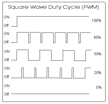
So basically, the longer the pulse width or high signal is on during the period, the brighter the LED will be. And inversely, the shorter the pulse width, the dimmer the LED would appear. So as per the below image, if we have a duty cycle of 100%, the LED would appear at its brightest. A duty cycle of 0% would turn the LED off.
Setting up PWM using MCC
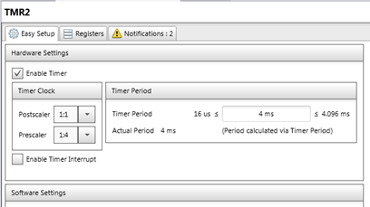
We can easily setup the PWM in the PIC16F18323 using MCC in MPLABX. In order to use the PWM we will need to add a timer to the peripherals, to be using in conjunction with the PWM peripheral. As I mentioned above, I want to run the PWM at 250Hz. The below pic is the setup of the timer in my MCC.
Below is the setup of the PWM in MCC. I have output the PWM onto pin RA5 of the PIC. You will see that in the PWM window in MCC, you can adjust the duty cycle value and it will give you the value which you need to input into the function that MCC generates, in order to get that percentage duty cycle. Here you will have to enable the PWM and tell it which timer it is using, timer 2 in my case. Another thing to note is the polarity of the PWM. I am not going to get into this now but it is basically used to adjust whether the square wave signal generated on the PWM pin is active high or active low. So if you are driving the LED directly off of the PWM pin (RA5), you would set it to be active high, which would also make more sense with the duty cycle not being inversed. I had it set to active_lo because the RECOM RCD-24-0.35 that we used to generate the signal on a 40V line, inverted the signal it received.


You might notice that the values for the duty cycle percentages are -1 of what the duty cycle * 10 would be. You can check the datasheet of the PIC you are using and it will give you the formula for calculating the duty value that you would need.
Using the MCC Generated Function
So after generating all the MCC files, there is a really easy function that you call to adjust the pulse width of the PWM. I have put a screen shot of the generated function below. As well as an example of it being called at a 50% duty cycle, using the value from the above pics.


That is basically it. I am not going to include all my button / LED and other code cause it isn’t really necessary. I have uploaded a short video which we sent as a proof of concept to the client, which can be found here – https://www.youtube.com/watch?v=7I3k1On7vuE
Driving the Actual LED Light
The client gave me a sample of the LED light they plan on using as well as the PSU they would like to use for the product. The issue now, is that the PSU they want to use is 40V. We found a really cool DC/DC-Converter or constant current LED driver, that will take an input of 40V from the PSU as well as the PWM logic at 5V and output a 40V PWM signal. You can get more info on the Recom DC/DC converter here – Recom Link
Below is a screenshot from the datasheet. You will see that they invert the PWM signal and that is why I had to change the PWM polarity of the chip output to active low.

Powering the PIC
Next we had to look at getting a DC/DC step down module to get the 40V from the PSU to 5V for the PIC. We found a cheap module, in the below pic, that would fit well into the product. Even though the module says it only takes 1.25V-35V, it is able to step down 40V.

